
What is Continuity Test?
Continuity Test is an electrical check that determines whether a complete conductive path exists between two points. A meter sends a small test current through a de-energized wire, fuse, switch, or connection. A low resistance reading or audible tone usually indicates continuity, while a very high or infinite reading indicates an open path.
Quick Facts About Continuity Test
Category
Electrical diagnostic test
Measured by
Resistance in ohms
Used for
Finding open circuits and checking connections
Common confusion
Continuity does not confirm correct voltage or circuit operation
Also called
Continuity check, Continuity test mode
Often discussed with
Electrical Troubleshooting, Electrical Inspections
Key Takeaways About Continuity Test
- A continuity test checks for an unbroken electrical path between two selected points.
- Turn off power before testing, because most continuity functions are not designed for energized circuits.
- Low resistance usually indicates a connected path, while infinite resistance suggests an open circuit.
- The test can locate broken wires, open fuses, faulty switches, and loose connections.
- A continuity reading alone does not prove that a circuit is safe or correctly wired.
Understanding Continuity Test
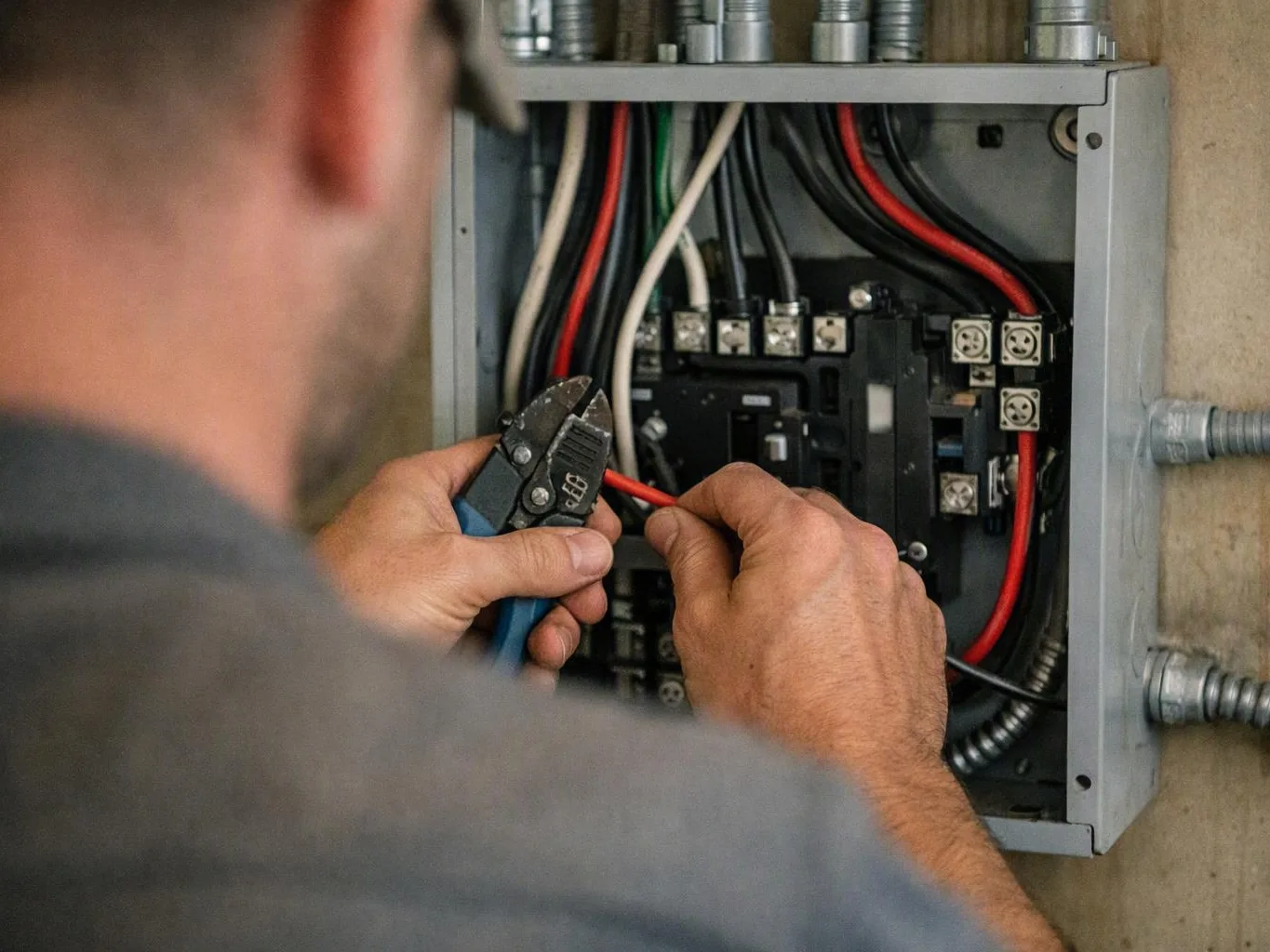
A Continuity Test checks for a complete path between two points. The test sends a small current through the path. It then measures resistance. Low resistance usually means the points connect. Very high or infinite resistance usually means the path is open.
Related glossary terms: Current, Ohm, Electrical Grounding.
Electricians commonly check wires, fuses, switches, terminal connections, and printed circuit traces. Many digital multimeters have a continuity mode. This mode sounds an alert below a set resistance level. The tone level varies by meter. The display reading still helps when the meter doesn't beep.
How Continuity Test Works, Is Measured, or Is Used?
Power must be switched off before testing. The circuit must also be isolated from other paths. The technician places one probe at each test point. The technician then checks the resistance reading. A reading near zero ohms suggests a short path. An overload display, open-loop symbol, or high value points to a break.
The meter's ohmmeter function supplies its own small test current. This differs from measuring voltage. Voltage tests need an energized circuit. They compare electrical potential between points. A typical workflow starts by testing the meter on a known connection. The technician then disconnects power and separates the component when needed. Next, they test the target path. They interpret the result using the circuit design.
- Test a wire end to end to find a break.
- Test a fuse across its terminals. This checks whether its element remains intact.
- Test a switch in open and closed positions. This confirms its operation.
- Test between conductors to find an unwanted connection. Disconnect parallel loads before reading the result.
Continuity readings can mislead when components create a parallel path. Capacitors, electronic controls, lamps, and connected loads may change the reading. They may also create a short-term tone. A technician may disconnect conductors or remove a component first. This helps the technician reach a sound conclusion.
Why Continuity Test Matters?
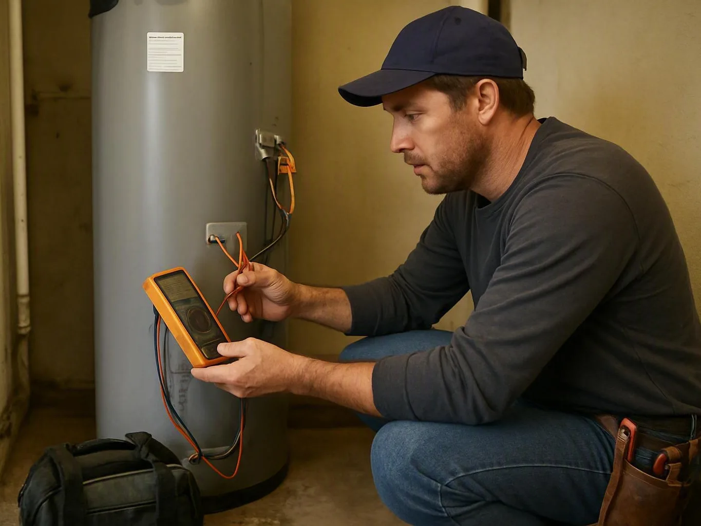
A continuity check helps separate a broken path from other electrical faults. It can identify a damaged branch circuit conductor, an open fuse, or a failed switch. It can also find a loose termination without random part replacement. This focused information supports safer troubleshooting. It can also reduce extra repair work.
The test supports quality checks after installation or repair. A technician may confirm that a conductor reaches the correct terminal. They may check that a bonding jumper remains continuous. They may also check that construction did not damage a cable. Continuity alone doesn't verify insulation condition or correct polarity. It doesn't verify conductor size or dangerous voltage.
When Continuity Test Matters Most?
Continuity testing helps when a device won't operate. It helps when a circuit seems open or a fuse fails to pass current. It also helps.electrical inspections, equipment repair, and new wiring work. Technicians also use it after drilling, remodeling, or physical damage. Test points should match the wiring diagram or intended component path.
Safety comes first because continuity testing usually needs dead circuits. A live circuit can damage the meter or cause a false reading. It can also expose the tester to electric shock. For complex systems, the technician may follow the circuit from its source. They check protective devices and controls along the way. They then confirm the fault with proper voltage and resistance tests.
How to Evaluate Continuity Test?
- Confirm the circuit is de-energized and verify the absence of voltage with an appropriate tester.
- Check whether the meter displays low resistance or a continuity tone across the intended path.
- Compare the reading with the component's wiring diagram and expected operating position.
- Inspect for parallel paths that could create a false continuity result.
- Look for damaged insulation, loose terminals, heat damage, or corrosion near the test points.
Related Concepts Compared
Continuity Test vs. Resistance Test
A resistance test reports the measured opposition to current in ohms. A continuity test is a quick pass or fail check that usually relies on a low-resistance threshold.
Continuity Test vs. Voltage Test
A voltage test measures electrical potential between points and normally requires an energized circuit. A continuity test uses the meter's internal source on a de-energized path.
Continuity Test vs. Insulation Resistance Test
An insulation resistance test looks for unwanted current flow through insulation and often uses a higher test voltage. A continuity test checks whether the intended conductor path is complete.
Continuity Test vs. Short Circuit
Continuity is expected through a closed switch or connected conductor. A short circuit is an unintended low-resistance path between conductors or between a conductor and ground.
Expert Note
A beep does not always mean a wire is healthy. A partially broken conductor may pass a low-current meter test yet fail under load. Check terminals, conductor condition, and voltage drop when the circuit must carry operating current.
Common Mistakes or Myths About Continuity Test
- Testing continuity on an energized circuit.
- Assuming a beep proves that the wire can carry its full rated load.
- Leaving connected loads in place and misreading a parallel path.
- Failing to verify the meter on a known connection before testing.
- Treating an open reading as proof of one specific fault without inspecting the circuit.
Continuity Test in Practice: A Real-World Example
A ceiling light stops working after remodeling. With power isolated, a technician tests the switch and cable end to end. The switch shows continuity when closed, but the cable reads open, directing the repair toward a damaged conductor rather than the light fixture.
Sources & Further Reading on Continuity Test
Related Services
Related Terms
Current
Current is the movement of electric charge through a conductor, device, or circuit. It's measured in…
Ohm
Ohm is the SI unit of electrical resistance. It measures how strongly a material or device…
Electrical Grounding
Electrical Grounding is a safety system that connects electrical equipment and circuits to the earth or…
Short Circuit
Short Circuit is an unintended low-resistance path that lets excessive electric current flow between points at…
Chris Miller Electric
Have Questions About Continuity Test?
Contact Chris Miller Electric for practical guidance on Continuity Test and related electrician work in Fort Wayne.